 |
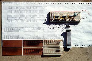
VU Meter Construction This picture shows the beginning steps in creating the VU Meter. The printout shows the routing for the PC Boards for both the control and display sections of the meter. The control section shown on the breadboard. The display sections are shown at various stages of completion. Each channel of the display uses three display boards with 10 LED's each. |
|
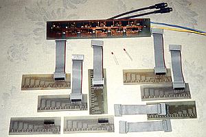
VU Meters completed Each channel of this stereo VU meter has 30 independent steps displayed with red LEDs. The control board was etched double sided. Each of the six display segments contain 10 LEDs and was etched from single sided PC board. Ribbon cable is used to connect the control board to each of the six display segments. I built a couple of extras as shown in the picture. |
 |
 |
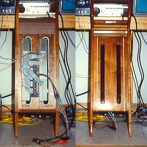
Overhead Console - VU Meters This picture composit shows both sides of the overhead console after the electronics were attached. Also in the console (not shown in this picture) is a control panel for the system which includes controls for each individual component as well as the main power and emergency kill switch. |